
Do what now?
So we have all these extra pins on the Raspberry Pi. These pins are known as GPIO or "General Input Output Pins". We can do some cool things with these pins in software. One of the things we can do is, with a python script, control whether a pin is a sensor for 3.3v, or if we're sending a signal of 3.3v on each pin. There's also another cool thing you can do, and that is send a variable voltage across a pin through a neat little trick called Pulse Width Modulation (PWM). PWM emulates a variable voltage by pulsing the maximum voltage (3.3v in this case) at a high frequency. In theory this will allow me to control my fan speed through code.
I say in theory though, because what I have is a 5 volt fan, and the GPIO pins only output 3.3 volts. I tried hooking up the fan to the GPIO pins directly, but 3.3v apparently isn't enough to get the fan spinning. It NEEDS a 5 volt pulse to go.
Well, now what am I supposed to do? I can't control the fan directly because I can't pulse a high enough voltage to get it to spin up. And I can't control the 5v pin, because its connected directly to power. I can't interface with it through python code. Enter the Transistor.
How transistors work is beyond my knowledge. All I know is how to wire one up to do what I needed it to do. Basically, when wired properly, a transistor works kind of like a relay switch. It has 3 pins, a base, a collector, and an emitter. When a voltage is applied to the base, it connects the collector pin and emitter pins. When the emitter is ground, and the collector is my fan in series with its 5 volt supply, it acts as a switch that I can control with a 3.3 volt pin.
Back to the internet! I ordered a pack of PN2222 transistors, some 5050 LED breakout PCBs, and some assorted wire for me to solder to. I followed along with this tutorial in order to figure out what needed connecting where. After some fine wire work, soldering and clipping of legs, we have my finished transistor module:
 All that remained was putting it into the case. Unfortunately I don't have any pictures of what it looks like in the case. I'll be diving in later to make another modification later this week, so I'll try to get a picture then. Suffice to say, it's become a bit of a mess. BUT, I have the ability to control my fan speed programmatically through python. BEHOLD MY CODE!
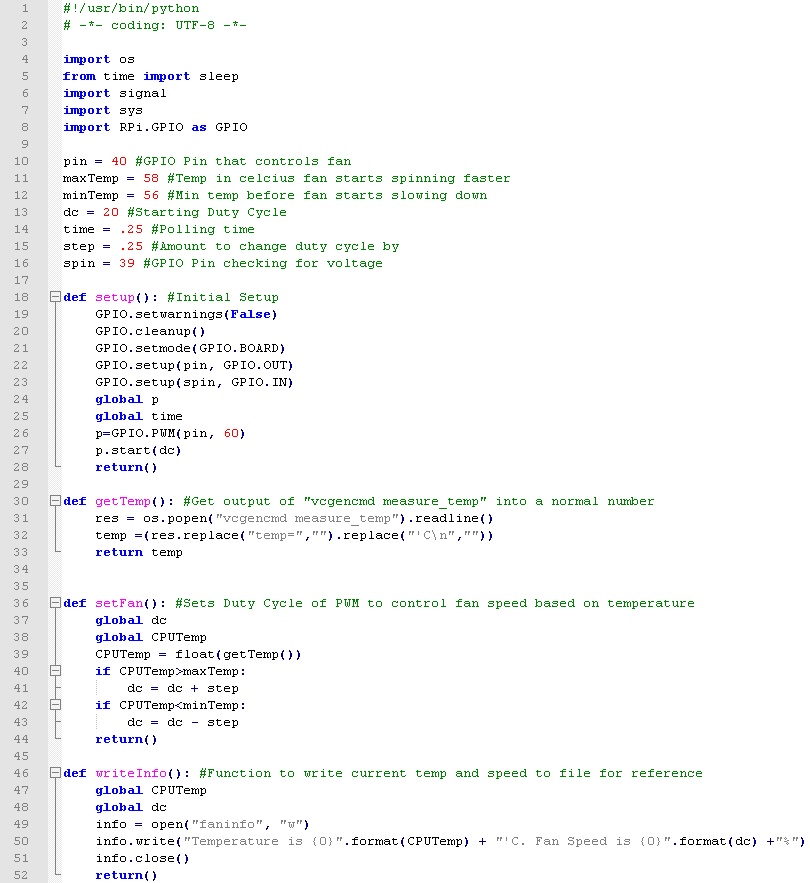

Sorry for the pictures. If you need to copy it for your project I have it here. There are a couple of extra lines of code in there for the next phase of this project, which I will detail in part 5.
So a basic explanation is that we import the modules we need at the top, followed by initializing some constants like what pin is connected where, how much I want the fan speed to step up or down as a percentage (that's your duty cycle, percent of time the pulse is on vs off). Then we define a few functions to get the temperature in a usable format, write temperature and fan speed to a file, and then run the meat of the code in a loop. Every cycle, we check the temperature. If its above my set max temperature, we'll increase the duty cycle by the "step" amount. If its below the minimum temp we decrease the duty cycle. This arrangement allows the temperature to sit between the low and high level with the slowest fan speed possible, minimizing fan noise. Then we wait (sleep) for a period of time and do the check again. I can tell you, after having run this for a number of days now, it works great, and its very slick.
In part 5, we'll talk about what happens when you hit the off button, and what SHOULD happen, and how we make what SHOULD happen actually happen. Seeya later.
No comments:
Post a Comment