Showing posts with label arcade. Show all posts

Tuesday, February 21, 2017

Taken by a Strange Mood, Part 5 - The shutdown problem

We're going to call this blog post "The Shutdown Problem".  The Raspberry Pi, though small in stature and large in utility, is in fact a full linux computer.  That means that all the things that come with a full linux computer apply, included the need to shut the computer down before pulling the plug on the power.  This isn't normally a problem because most normal people just have their pis plugged into a wall outlet until they've actually done a manual shutdown.  I don't have this luxury.  My Pi is powered by the TV itself, and when I hit the off button on the TV, so goes the Pi.

This is a problem.  In my setup, there is no guarantee of a safe shutdown.  This TV is ultimately going to live in my kids' playroom, so they're just going to be hitting the off button when they're done with it.  If I don't do something about this problem, we'll eventually get file system corruption, and I'll have to start the whole process over again.  Fortunately, there is a solution.

I'm going to take this moment to apologize for not having this blog post up sooner.  I believe its been nearly a month or more since my last post.  Its been that long because its taken me that long to get my elegant solution actually working.  I went through many trials, more errors, and intermittent success before working out all the kinks.  And now that I have, I can officially call this project "finished".

So, where to start?  I guess we'll define the specific problem.  When the power goes off, my pi goes off, without a shutdown.  How do we fix it?  Shutdown at power down.  But we can't complete a shutdown at power down because power is already down.  We'll need some power stored to keep the pi alive during shutdown, and we'll need a way to sense when power has been cut in order to initiate the shutdown automatically.

Solution#1:  In line rechargeable battery.  You know? One of those big secondary batteries that you get to charge your iPhone when you don't have a wall to plug into.  Fully packaged, simple, easy.  It also won't work.  When a Pi shuts down, it isn't doing a true shut down, its doing a system halt.  Effectively the same thing, but different enough to give me trouble.  Once a pi is halted, the only way to unhalt it and cause it to boot is to pull the plug, or hit the reset pins.  Unfortunately, I didn't know about the reset pins until after I had already permanently glued my pi into the TV.  I couldn't reach them.  So since we can't boot without pulling the power, that means I wouldn't be able to start up the pi again until the battery completely died. With a battery the size of the ones available, even the smallest ones, that could take hours, if not days or weeks.  We need a better solution.

Solution#2, provided by the nice folks at the adafruit forums: create a supercapacitor circuit and place it in line with the power supply.  I'm not going to go into the nitty gritty of capacitors, but suffice it to say that they are capable of storing energy, and then releasing it when the charging voltage is removed.  This is a much better solution because capacitors charge relatively quickly, and more importantly for my application, they also discharge relatively quickly.  After I did some math and estimations I determined I needed about 10 farads worth of capacitance, at 5 volts.  Oh, and the capacitor also needed to be able to discharge with a current of at least 1.5 amps.

I jumped onto the internet, to get buying.  I found one that I thought was perfect.  A single 5V capacitor that could store like 15F.  I bought it.  It came in.  I wired up my circuit.  I plugged it all in.  I let it charge.  I pulled the plug. It didn't work.  I double checked the data sheet: this capacitor was only capable of supplying 35 miliamps.  Back to the internet.  This is when I hit a snag.  I could not find a single capacitor rated at 5V, 9-15F, and also 1.5 amps or more.  But I did find capacitors at 2.7V, 30F, and like 9 amps (it was alot, more than I would draw).  This complicated the circuit, because now I'd need two capacitors in series.  Caps in series add their voltages, just like batteries.  But they also half their capacitance. (Actually, its a formula. 1/C = 1/C1 + 1/C2 + ...)  The other problem with using more than one capacitor is that, due to manufacturing tolerances, no two capacitors are exactly alike, and if they are different enough they will be imbalanced, and eventually one or both of them will break.  So I needed a balancing circuit.

Behold My Circuit Diagram. Yes, I know my diode symbol is backwards.
Another problem with capacitors is that when they are completely discharged, they look like a short circuit to a power supply.  And most supplies freak out when they think they've been shorted.  Some burn out.  Others just cut their supply so as to not burn out.  This is what mine does.  How to get around this?  You have to put a small resistor in front of the capacitors so that it no longer looks like a short.  It has to be small because the resistors themselves reduce the amount of charging voltage available to the caps, thus reducing the maximum charge I can put into the caps.  So 1 or 2 ohms is sufficient.  Unfortunately, the smallest resistors I had at the time were 100 ohm.  And I discovered that this was way too much resistance.  What's a guy to do?  I took all 11 of my 100 ohm resistors, twisted their ends together, and put them in parallel.  This produced an equivalent resistance of just under 10 ohms.  This worked much better, but was not ideal.
Actual Circuit.  The two large caps are connected, the smaller one isn't.

The other problem with these resistors and capacitors was that if the resistors were just put straight into the charge lane, they'd also be in the way of the discharge lane, and reduce discharge voltage, giving me headaches.  The solution to this is to put a diode in parallel with the resistors.  The diode prevents current from skipping over the resistors when charging, but allows current to flow around the resistors when discharging.  You see, capacitors discharge in the reverse direction of charging.

So, after much trial and error, I finally had a circuit put together that actually worked.  Mostly.  See how my large caps are bent over in the picture.  Turns out this caused me a world of pain that I wasn't able to correct until today.  You see, when I bent the pins on the caps like that, I accidentally damaged whatever internal connections there were.  Damaged, but not broken.  So they worked... sometimes.  It was very frustrating, and I blew up 2 different voltmeters while trying to figure out just why I was having the trouble I was having.  Anyway, here's the final circuit in place.

I'm skipping over a huge part of this, because its less interesting because it worked the first time, every time.  The method for sensing a power down was super easy.  I picked of a "voltage regulator".  The specific regulator I got takes a 5-15 volt signal, and converts it to 3.3V, which is the logic level of the raspberry pi GPIO pins.  I connected the regulator straight to the original 12V supply (before my 5V converter), put a large (1000ohm) resister in series with the 3.3v signal, and connected it to a GPIO pin.  Then, I have my fan control script watch that pin, and whenever it goes from on to off, we initiate a shutdown.  Here's how it looks.  You can also see my fan control transistor in this picture too.

That was the easy part.  Here's how the whole thing looks now that its done.

So, it was quite a struggle, but I persevered, and I was all done.  Or so I had thought.  After I tested it, I put everything back together, hooked it up, and it worked great.  All the emulators running on the Pi ran without a hitch, and when I killed the power I could verify from the activity lights that it kept alive through the shutdown.

And then one day, it didn't.  I was getting some software set up, and I noticed that the standard raspberry pi low power warning was constantly popping up on my screen.  "Huh", I thought.  I didn't think my little circuit would pull that much current, especially not after it was charged up.  I turned off the power and checked the activity lights.  Dead.  Nothing.  No shutdown.  Something was broken.  Turns out, I broke the capacitors when I bent the connectors, because the bend point was actually just inside the cap, instead of outside.  Oops, rookie mistake.  I bought two more this week, and just got finished installing them.  They charge up faster, discharge consistently, and no more low power indicator.  Thank goodness.

I hope you all enjoyed this little technical journey.  Here's some pictures of the finished product again.


If you want to see ALL the pictures from this build, I've linked them on a google plus album here.  Thanks for following!

Monday, January 2, 2017

Taken by a Strange Mood, Part 3

As I intimated at the end of Part 2, there were problems that extended this project.  Sure, I had a working embedded Plex image running on the Pi, but I had more ambition for that.  I downloaded and burnt the latest RetroPie image to an SD card and got that started.  The original plan was to have 2 SD cards: one for games and emulation, the other for movie watching.  Then I found out that Kodi could be installed under retropie, and that there was a brand new Plex plugin for it.  Once I discovered that, I stopped using the Plex image altogether, and have stuck with retropie.

This is not a blog post about setting up retropie, however.  It went pretty standard as long as you follow along with their instructions on their page, so I won't address that.

No, the problem I started seeing almost immediately is app crashes, freezing, and unexpected behavior.  The IC on the Raspberry Pi 3 is rated at a max temperature of 80' C.  When I checked my temperature, even at idle, I was running mid 70s.  Yipes.  Too hot!

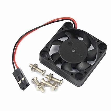
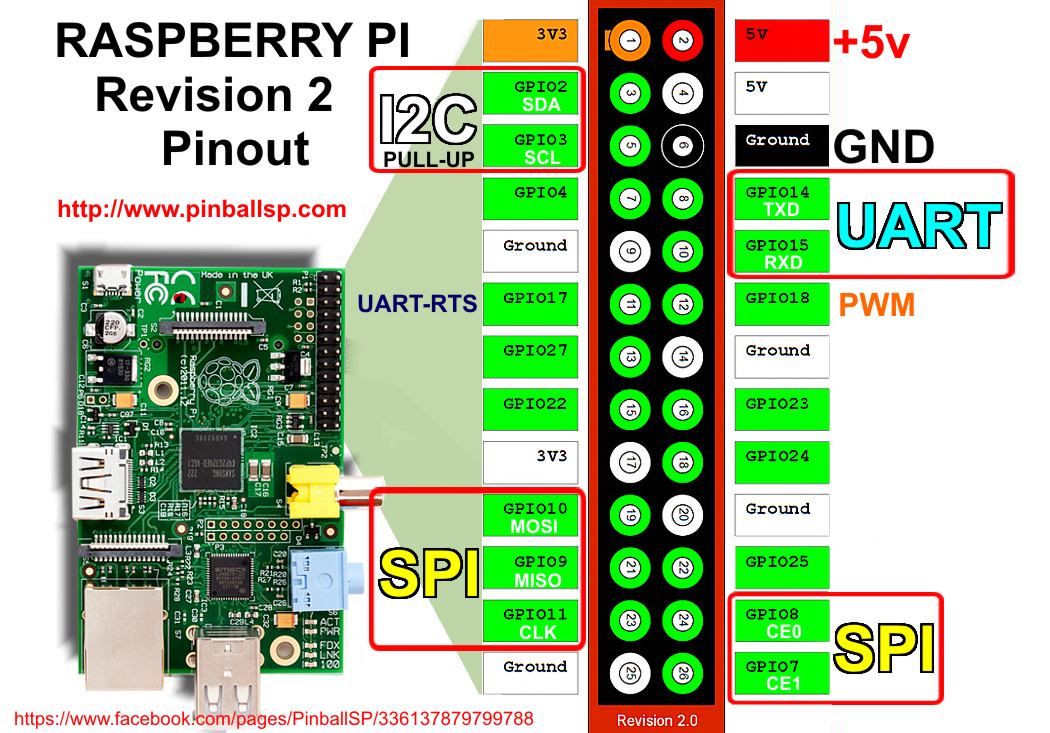
Even though the RPi shouldn't need active cooling under normal circumstances, I was not operating under normal circumstances.  Ambient temperature inside the TV was affected by the TV electronics heating up, so the pi could not passively cool effectively.  I needed a fan.  At 5V, 0.2A max, this fan seemed ideal.  So I bought it.  It can plug directly into the 5V rail of the GPIO on the pi, and connect to ground. There are 2 pins on the GPIO that seem like they were designed for just this, pin 4 and 6.  All we need to do now is open up my case, and install the fan.  Sounds easy, right.  Well it would have been easy, except that I had ALREADY permanently affixed the thing inside my TV, so I couldn't remove it to get the top of the case off, or do anything else much with it.

Fortunately, the case didn't snap closed, and there was just enough wiggle room for me to be able to fit the small fan into the gap I could create between the top and bottom of the case.  Here's the other problem: no vents in the case.  Time to get out my drill!
I picked the closest sized coring tool I had in my drill bit set, lined it up, and went to work.  Even at slow speeds the drill didn't so much cut through the plastic as it melted through.  My plastic chips were all melted together, and some of them are still stuck inside the case.  Now came the hard part, getting the fan in there, and also mounting it to the inside of the top half of the case.


Case with fan hole cut.
I ended up using two small allen wrenches as feelers to position the fan under the hole.  Got another JB weld mix going, and then tried to hold it in place for 15 minutes. That didn't happen.  I was shifting the fan all around as I tried to hold it steady.  I needed a more permanent temporary way to hold the fan in place while I waited for the epoxy to cure.  In came my good old friend, Masking Tape.
Pull up, apply masking tape, hope it doesn't fall


Now that I had the fan in place, I needed to do something about the metal plate that covered the Pi here.  You see, a fan doesn't do you very much good if it doesn't have any access to ambient air to blow.  I sized up the location of my fan relative to the edges, and laid out my new hole pattern I was going to drill.

Hole Pattern


Drilled holes.


Holes in plastic cover
I think I messed up the label.

By the time I was finished drilling holes, my JB weld finished setting, and it was time to bring it all together. I plugged in the fan into the two pins I mentioned before  Closed the whole thing up, and turned it on.  Fan spun up.  It sounded like the blades were brushing something, because it was loud, and getting louder.  Even completely covered up by the case, running at 10k and brushing something with each blade on every revolution, this thing sounded like a small dustbuster.  This was No Good for a media smart TV.  I opened the thing up again to see if I could find what we were running into.  Turns out that this particular fan doesn't keep its wires away from the fan blades very well, and the blades were brushing the wires.  This took lots of finagling over several attempts to get the fan where it wasn't hitting itself when it spun up.  But even then the sound was very loud.

I checked my temps, and this thing was running cool.  I want to say it was less than 55' C under full load with the fan fully spun up.  So it was doing its job, just at a audible level I was not happy with.  Remember how I used JB weld again, and this thing was now a permanent resident?  Yeah, time for some more engineering.

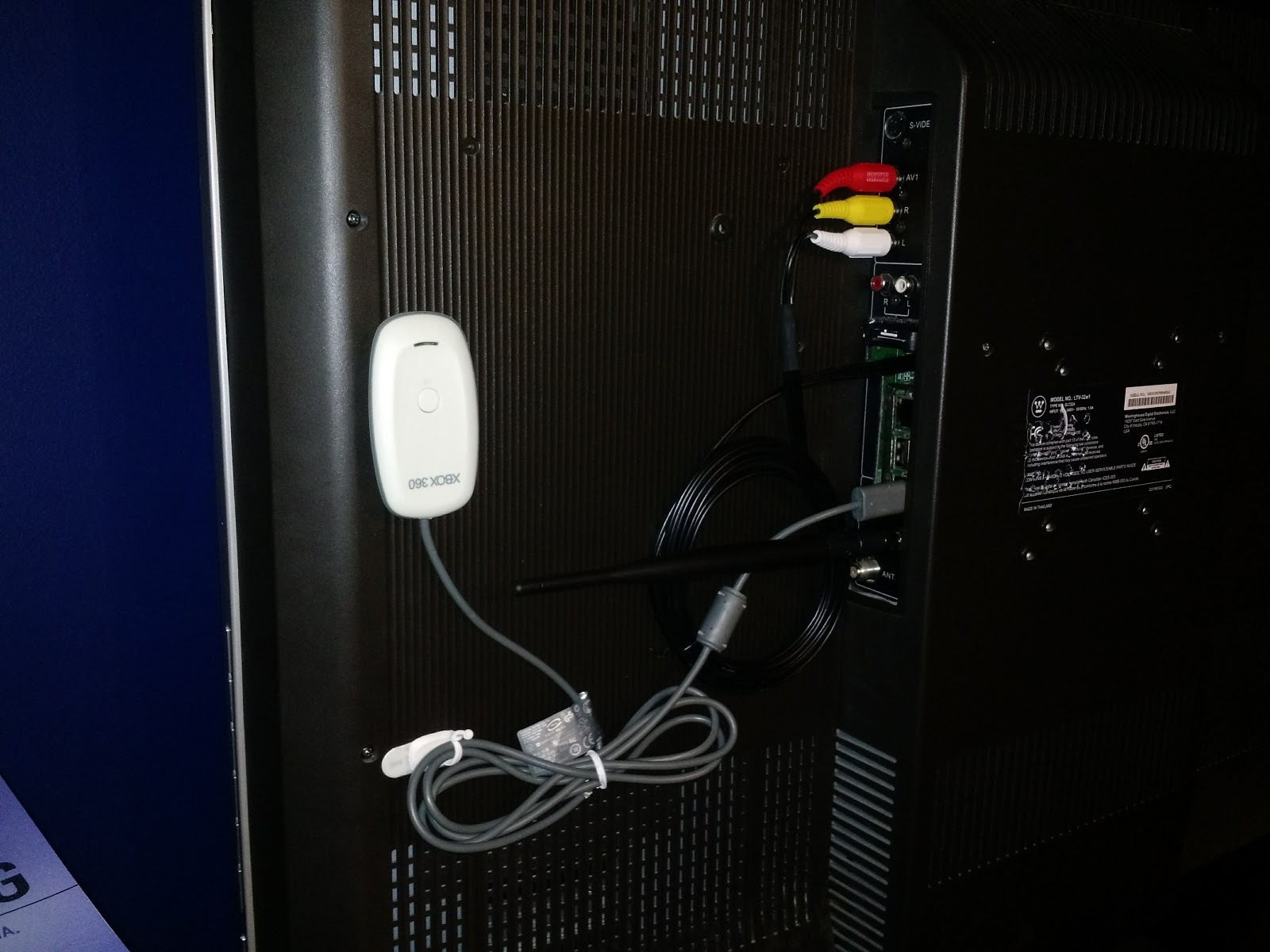
I almost forgot to mention.  Before all of this I was getting a lot of noise out of my speakers.  Anytime something would be busy on screen, or there was disk activity, I'd hear a little noise.  Turns out the AV cable I used wasn't of the highest quality, and in addition the way I had my power supply connected meant that my Pi wasn't getting properly grounded.  I fixed that (mostly) by adding a wire from a ground GPIO pin to the case.  No, that solder joint didn't hold, but the wire is sandwiched between the side plate and the top plate, so it stays in place.  And my noise was reduced significantly (but not totally).  Too bad that AV cable was now a permanent resident.

In part 4, you get to find out how I dealt with my obnoxiously loud fan.

Wednesday, September 16, 2015

Points!

Being an arcade monkey ball style game, of course Eruptoid has Points.  It'll have a high score tracker that I'm hoping to be able to upload to a global database that will track scores of players by region and player supplied string (such as name or initials, or maybe facebook name/google+ profile name.  Haven't decided yet).

Anyway, while I was messing around the the UI, converting it from OnGUI to UnityUI, I noticed my points weren't working.  Turns out it was because I forgot to associate the correct score text fields with the right public variables in the game controller script.
Total Score at the Bottom
I had TotalScore in the Level Score TXT field.  Oops

Well, after I fixed it all up, I noticed that my scoring was rather boring.  The ice cubes I currently have set to be worth 100 points.

And then, upon completion of the level, you are awarded points based on the amount of time remaining.  And I had total score calculated only after the level ended, instead of having it increment every time you got new points.

First thing was first, getting total score to keep up with level score.  I had 3 variables, the HiScore variable which was populated from playerprefs, and represented the highest score attained on that level.  Then I had the levelscore variable, which represented the current score on that level.  And then we had TotalScore, which was an accumulation of the scores of the current play session.

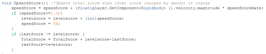
Getting the TotalScore to move with the level score wasn't too difficult.  I just had to track the levelscore variable, watch when it changed, and then change the TotalScore variable by the amount of the level score variable.  The code looks something like this:
So, lastScore is an integer that's set to the current levelscore at startup.  Then, every frame, we compare the value of lastScore to levelscore (which changes every time you get a cube), and then if a change is found, we add the amount of change to the TotalScore.  Finally, we set the lastScore and levelscore variables to be equal so that we can continue to monitor changes in levelscore based on its new value.

As I said, once I got to play testing the new arrangement, I noticed that scoring was rather boring and predictable.  Not very arcade-y.  So I thought "why not award points based on how fast the ball is moving".  This was slightly more complicated than the above.  I basically ended up using the velocity of the ball, multiplied by a fudge factor, in order to get a point value, which is added to the score every frame.

Trouble was, my scores are integers (int), and the velocity of the ball is a floating point number.  Since integer math truncates floats to their nearest int, I was getting no points added until I reached a certain speed threshold, and then I was suddenly getting lots of points.  The solution I took was to decrease my fudge factor by a factor of 10 (from 0.1 to 0.01), and then store a floating point variable that, once it reached a value of 1 or higher, would then be added to the level score, and thus the total score through the code above.  I then packaged the whole process into an UpdateScore function, which you can see here:
SpeedScoreRate is my public float fudge factor.  Making it a public variable means I can change its value from the Unity inspector, instead of having to open up the code and edit it directly.

So, now that its all said and done, I call the UpdateScore function once every frame in the Update block, and the player gets awarded extra points for going fast.  Scoring is now a lot less boring.