Sunday, January 1, 2017

Taken by a Strange Mood, Part 2

I forgot to mention one major minor detail from my parts build.  You see, the Raspberry Pi 3 has build in WiFi and Bluetooth.  That's good.  The bad news is that the whole assembly will be trapped inside the metal chassis of my TV.  Not very good for wireless signals.  Fortunately, there is an external antenna mod you can do on the Pi, with questionable legal ramifications (since you're messing with an FCC approved device, and thus potentially voiding the Pi's certification).  I followed along with the guide here.  I ordered the antenna parts. I was going to attempt to solder on a U.FL connector to the bottom of the Pi, but when I got the parts in hand I determined that the connector was WAY too small for my shaky hands and giant soldering iron.
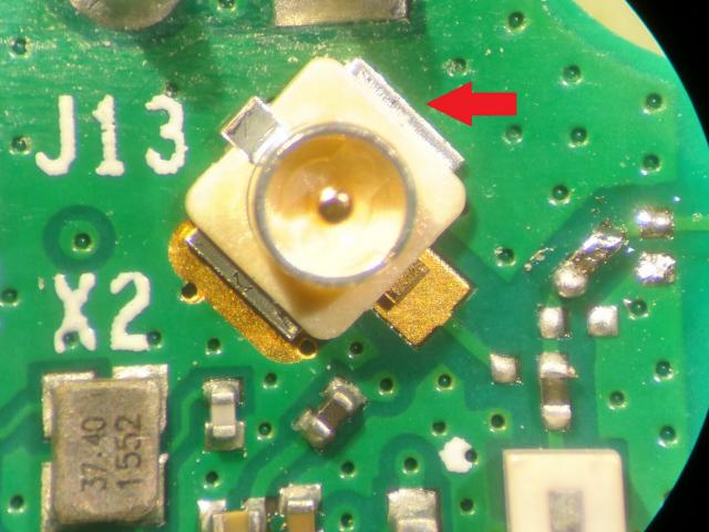
Doesn't look so bad on the guide.

Oh wait, that spot is smaller than a fingernail.

The solder point for U.FL is those two copper pads.  You also need to move a Zero Ohm resistor, which is about the width of 5 hairs.  How about Nope!

So I went with plan A on the guide: top mount.  I broke off my Pi's ceramic antenna and soldered on the lead for my coaxial antenna.  This was a major ordeal, since my solder did not want to stick to either the ground plate, and I had to resolder the thing at least 3 times before a had a solid strong connection.

Ok, now that we have that detail out of the way here are the parts before assembly:


And here's how they're going to look placed in the TV chassis:

Parts arrangement, so ensure everything would fit.
Original (removed) plug on left

I originally planned to have the SD card ribbon sit just above the USB ports on the Pi.  Unfortunately, once the added space of the plastic case was added, there was no room at all for this configuration.  I ended up moving it above the Pi (in the direction of the top of the TV).  Before I did any cutting, however, I needed to make sure that my 12V to 5V would provide enough consistent power to operate the Pi off of.  The 12V connection come on at TV power on.  I went ahead and made my power adapter connector, and modified the cable to have the correct sized USB plug on the end.
Soldered leads together.


Wire with electrical tape.


So, that took care of the business end of the 5V downverter.  I enlisted the help of my lovely wife Nancy to ensure that the Pi would indeed boot when all the parts were connected together.

Holding the leads to the power supply!

You can barely make it out, but the red LED on the pi is lit.  Our power supply works!

The first cut spot.
With my power connection verified, I felt now was the time to start cutting.  I marked where I thought the SD card ribbon cable would come out with red dry erase marker and got out my dremel. "But Specter," you say, "What about all the metal shavings!  Won't they get all over the motherboard and cause all sorts of shorts and damage?!?!"  Why yes.
Dust "Collector"
But I have this brilliant plan!  I'll stick a big rare earth magnet on the other side of the chassis inside a plastic bag, and it will collect all the metal dust for me!  What could POSSIBLY go wrong?  Did I mention that I was in a strange mood.


Long story short, don't do this.  Ever.  While I was able to collect a lot of the metal dust the dremel produced, it was impossible to collect ALL of it, and there was a fine coat of dust all over the sensitive electronic components.  I got as much up with the magnet as possible, but then I had to get a damp rag out and literally dust every surface I could reach.


And now.... the first incision.

I didn't destroy the project with this boneheaded move, luckily.  But for every subsequent cut, I took the bracket off the chassis, took it outside, and did my cutting there.  And boy am I glad I did.  This was 1/16" thick STEEL.  It took a relatively long time to do all the cuts, and then buff out the burrs and do fine trim ensuring consistent sizing.

While I had the plate off, I went ahead and drilled a hole for my external antenna, down near the existing coaxial "antenna" spot.  Here's how it all looked after all the steel cutting and parts approximately in their final places.

New Window
Components in place
JB Welded.  And proper plug placements
You can see in the above picture that the clear plastic case has no venting to speak of over the CPU (which has a heat sink).  This will come up in part 3 of this series.  Now, the only thing left to do was JB weld it all together.  The container claimed that the compound would take 15 minutes to set, and 30 to be at a machinable cure.  Perhaps I got a bad mix, but it took at least 30 minutes for it to set for me.

Anyway, I got it to set, and got all my piece parts in place where I wanted them.  The power supply cable fit nicely in the crevice between the TV PSU and the TV motherboard.  I was able to snake it up and around to the pi plug without it getting in the way of anything.  The SD card ribbon wrapped up with a rubber band.  The AV cable JUST fit between the SD card port block and the pi itself.  But this cable is now permanent.  The plastic case is welded to the chassis, as is the SD card port, and there's no room now to remove the plug from the pi.  I sure hope that I don't regret going with AV for my video.  Time to close it up.


That dust was from the dremeling before.  Yuck.

The final plan is going to be to wall mount this TV in my kid's playroom in 6 months or so.  I'm a little bit concerned that the meat I took out of the side plate might have compromised the strength of the VESA mount plate that attaches to it.  Here's hoping it doesn't fall off the mount.  I'll let you know if it does.  Only thing left is to plug it in, turn it on, and see if it works.

It Works!  Plex image from Part 1 running clearly!
I wish I could say that this is the end of the tale.  That this ended here, with no further problems, and that this mod only took me 2 days to do, instead of 3 weeks.  But I can't.  There will be a part 3 of this series. Perhaps even a part 4 and 5.  But though the struggle was long and epic, the results are awesome.
Taken by a Strange Mood, Part 1

About two or three weeks ago I was taken by a strange mood.  We had our annual Christmas party, and I decided "wouldn't it be great if I could have movies in the back of the house as well as in the front."

Westinghouse 32" TV.  Collecting Dust.
We have this old 32 inch, 1366x768 Westinghouse LCD TV.  It used to be our primary TV (and was our very first flat panel HD television).  It doesn't even have HDMI ports, it's that old.  It served us well in its prime, but it has since been replaced by a 47" LCD (which was struck by lightning) which was replaced by a 55" Sony Bravia (the old version that weighs like 80 lbs and is 6 inches thick).  When we got the Sony, the Westinghouse became the bedroom TV, where it served admirably until about 2 years ago, when I wanted a chromecast for the bedroom.  Since it didn't have HDMI ports, I ended up buying another TV (42" RCA, I think), and so the old reliable Westinghouse was put in a back room to someday be used for something, probably.  I got my spare Raspberry Pi out, connected it to the TV's DVI out, with RCA audio, and burnt an embedded PLEX image to a spare SD card.  It booted, but the PLEX image did not know how to handle 1366x768 properly. Christmas party TV was a bust.  But there would be other parties.

Then, I got a brilliant idea!  Why don't I use a raspberry pi to turn it into a smart TV.  And not just a smart TV, but a retro game playing, plex movie watching smart TV.  It might work.  It could work.  And after I checked out the back of the thing, I might even be able to mount the Pi INSIDE the TV.  MWAHAHAHAHAHAHA!  Did I mention it was a strange mood?  I wonder if other engineers get these.

I took my existing RPi that I use for my backup server out of its case and opened up the TV, just to size it up.

Low and behold, not only was there space for the Pi to sit, but it looks like there was an entire area of this particular TV PCB that was unused (probably for a model with more features).  Now that I look at the pinouts in this area, it looks like it might have been a SCART input, or something similar.  You know, one of those TV connections that nobody knows about unless they work in media and television.  This is where I checked to see if the pi would fit.  Spoiler warning.  It did.  The next thing I needed to do to make this viable was find me a 5V power source inside the TV that I could power my raspberry pi off of.  I checked numerous plugs and connectors, and found several 5V spots.  Problem was, evertime I checked across them, the TV would shut down after a moment.  These were no good.  I then took a look at the power supply, and what to my wondering eyes appeared, but an unused, 4 pin connector.  I got my voltmeter out and read across the pins.  Two of them were ground.  Two of them were 12V.  But they didn't cause a TV shutdown when I read across them.  If I could just get a voltage downverter, I could connect here.  If only there was something you could buy that took a 12V input, and output 5V for charging a cell phone... like... a car charger... TO THE INTERNET!!!!!

The strange mood was in full swing now.  I was powerless to resist this new mania.  I found the perfect device here. Only problem was it had the wrong kind of USB plug on one end.  No matter.  I have a soldering iron and spare micro-usb cables all over the place.  The other problem was I had no idea what kind of plug that was.  Fortunately, the nice folks at the Adafruit forums came to the rescue.  I got on the amazon and ordered this, a Raspberry Pi 3, along with a clear plastic case.  The USB and Ethernet ports would face out of the TV chassis just below the AV1 input.  The trouble with this is that the micro-sd card is in the opposite side of the pi, and would be facing the inside of the TV chassis, completely inaccessible without opening the TV up.  I really didn't want to open the TV every time I wanted to try a new Pi image.  I wonder if they make Micro-SD Card Ribbon Cables?  They do.

Two questions remained.  How did I want to hook up the AV from the pi, and how was I going to get it all to stick firmly inside the TV chassis.  After much deliberation, and the bad DVI experience I had before, I decided to just use the Pi's AV out and connect to the AV1 input on the TV.  I kicked around the idea of wiring it directly, but ultimately decided to just use a cable, run it outside of the chassis, and into the inputs on the outside.  This would allow me unplug if I ever wanted to use the AV port for something else in the future.

As for how I would stick it all in there without worry, I decided to go with JB-Weld epoxy.  I may ultimately regret going with such a permanent solution, and it did make a few future mods more difficult.  But I won't have to worry about this stuff falling out of the TV ever.  And I mean EVER.  Next time, I'll show you how it all came together.

Monday, November 21, 2016

Updates!

Hey all, just wanted to give you an update.

I won that contest that I mentioned earlier for the ultra small computer case.  I was on edge for a while there, because some of the other entries looked really good.  But while they all looked good, I don't think they would have been functional without a LOT more engineering work done on them. Anyway, here's what it looked like finished. Had a lot of fun putting this together, and big thanks to Ed who requested the contest for choosing me as the winner.

I have another update as well.  As I type, I'm uploading another version of Cubix Rube to the google play store.  Once updated you'll find an improved rubix cube experience, with more intuitive face selecting, pinch to zoom functionality, as well as a short solving tutorial thanks to how-to-solve-a-rubix-cube.com.

If you like rubix cubes, please check it out, have a download, and let me know what you think via reviews or comments on this blog.  I'll talk to you guys later.

Wednesday, October 19, 2016

And Now for Something Completely Different

Look at that.  Think of beauty, isn't it.  What do you mean you don't know what it is?

OK, so I entered a design competition on this site called cadcrowd.  Its a freelance CAD and design websites, where people who need something engineered for them on the cheap put up some dollars, and then the community of designers submit ideas in hopes of winning those dollars.  Anywho, one buyer was looking for a design for an ultra small Mini-ITX case, and I thought this would give me a chance to flex my old engineering design muscles.  He was looking for a case that weighed in under 9 liters of displacement, and would fit a full sized video card and  M.2 PCIe SSD.  Most of the other folks submitted designs that were 9.5-10L.  That sweet puppy right there is 8L.  Its actually my second concept for this project.

The first project placed the video card where it belongs, right inside the PCI-E slot directly on the motherboard.  The buyer is using a low profile heatsink/fan combo, so I was going to place the power supply directly above the motherboard (with some clearance for airflow).  I got everything laid out and took a measurement on my displacement: 10.5L.  Back to the drawing board.

Motherboard Cavity View
So then I came up with this concept.  I had seen some other small case ideas that involved using a PCI-E ribbon cable to basically move the video card in an orientation where it could be over or under the motherboard.  I decided to put a central "spine" in my case that the motherboard would attach to on one side, and the video card on the other.  The PSU would then have to locate in front of the motherboard, and the case would then be long enough to accommodate 10.5" long video cards.  Because of the somewhat "exotic" location for the PSU, I needed to source parts and a cable for the inside of the case, not at all dissimilar to the ML07 and RVZ cases from Silverstone.

GPU Cavity View
The whole case is made from sheet aluminum, with a brushed finish.  The spine is 3mm thick, and the outside panels 2mm.  The spine has a spot for the psu to attach to, and the spine itself will screw in to the side/bottom panel.  The back plate is actually welded/brazed to the spine.  Outside panels are well ventilated.

The only thing left to design is the front panel hookups (lights, buttons, and USB ports).  That is a whole design challenge in and of itself, since you can't really just buy a pre-made arrangement.  I think I'm going to have to design the button and light placements myself, and hope that I can make it look good.

Case with Panels
Here's hoping that I do well in the contest.  Wish me luck!